To realize the model of dilatant decompression for oil and gas bearing horizons, the following equipment has been developed:
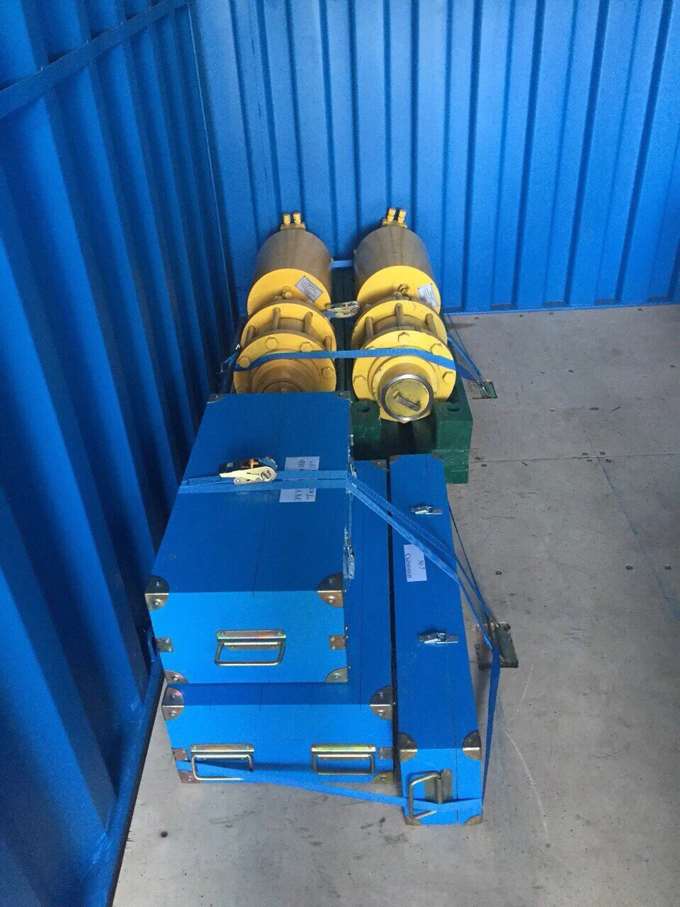
High-Frequency Pulsed Wave System with Hydraulic Pulse Generator

"HYDRAULICS -1H"
Technical Specifications of the "HYDRAULICS-1H" Unit:
- Impact Frequency: 33.3 - 66.7 Hz ( 2000 - 4000 strokes/min);
- Impact Energy (at a frequency of 33.3 - 66.7 Hz): 264 J;
- Impact Power: within 14 - 22 kW;
- Overall Dimensions (L x W x H), mm: (330 х 337 х 1146);
- Unit Mass: 220 kg;
- Well Treatment Depth: up to 5000 m;
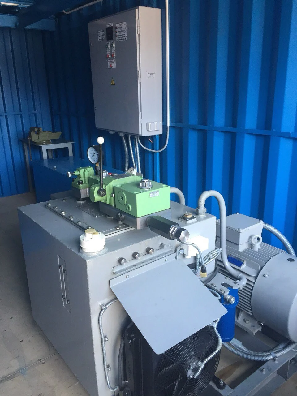
The energy source for the “Hydraulics-1H” hydraulic unit is the MS 160 oil station with a 40 kW electric drive.
Technical Specifications of the "PNEUMATICS-1P" Unit:
- Impact Power: not less than 4.3$ kW;
- Pulsed Pressure generated by the unit's generator: 20.0 - 30.0 MPa;
- Pulse Frequency at 0.6 MPa air pressure: 33.3 Hz ( 2000 strokes/min);
- Overall Dimensions (L x W x H):mm (295 х 422 х 930 );
- Unit Mass: 165 kg;
- Well Treatment Depth: up to 3000 m;
The unit operates from a compressed air source with parameters: pressure $0.4 – 0.7$ MPa, flow rate 3.4 m3 min/kW.
High-Frequency Pulsed Wave System with Pneumatic Pulse Generator

"PNEUMATICS -1P"
The Specified Equipment is Designed for:
- Restoring and increasing the flow rate (production rate) of oil, gas, and gas condensate wells.
- Increasing the injectivity of injection wells
- Enhancing the permeability of the near-wellbore formation zone and the interwell space of rock masses in situ.
- Eliminating gas and solid formation damage (colmatation) in the reservoir and equipment.
- Releasing zones of abnormally high pressure.
- Well completion (or well development).
- Bringing wells from the idle stock back into operation.
Effective radius of horizontal action: 300 m.
Recorded radius of wave propagation through the formation: 1200 m.
Vertical propagation of action: 0.5 m.

The operating principle of the system is based on acting on the rock formation with directed power pulses. These pulses are generated above the wellhead by the pulsed-wave unit and transmitted to the target productive formation through the column of working fluid in the tubing string (Tbg), which serves as a waveguide. Subsequently, using reflector containers, the power pulses are directed into the required productive horizon.
Stages of the well treatment process
- І. COLLECTION OF MATERIALS AND WORK PLAN DEVELOPMENT
- 1. Collection of materials for candidate wells and selection of wells.
- 1.1. Well passport data and operational documentation.
- 1.2. Materials on geophysical and hydrodynamic studies conducted in the wells, including logging diagrams and refinement of reservoir properties.
- 1.3. Perforation reports of the productive formation with precise interval specification.
- 1.4. Results of processing and interpretation of geophysical data.
- 1.5. Well inclinometry data.
- 1.6. History of geological and technical interventions and their effectiveness.
- 2.2. Development of the work plan for the well capital repair.
- ІІ. WELL CAPITAL REPAIR EXECUTION
- 1. Preparatory works (performed by the Customer’s TRS crew under the Contractor’s supervision).
- 1.1. Measure formation pressure (P_f).
- 1.2. Shut in the well with formation water.
- 1.3. Test well acceptability.
- 1.4. Pull all downhole equipment, measuring the tubing (NKT).
- 1.5. Run the reflector container into the well with control measurement of the tubing, ensuring careful threading and alignment.
- 1.6. Precisely position the reflector container in the target interval using a coupling locator.
- 1.7. Equip the wellhead with a blowout preventer; seal the tubing with a ball valve (bore diameter ≥ 60 mm).
- 1.8. Install the impulse-wave unit on the wellhead.
- 1.9. Restore fluid circulation. After stabilization, start the unit’s hydraulic drive. Route fluid from the annular space to a collection tank.
- 2. Work execution with power impulse waves (performed by the Contractor under Customer supervision).
- 2.1. Treatment is carried out in the required perforation intervals, from the bottom to the top, in 0.5 m segments with specified frequency, impact energy, and treatment duration.
- 3. Final stage of works (performed by the Customer’s TRS crew under Contractor supervision).
- 3.1. After completing the treatment cycle, run tubing to the bottom, flush the well with formation water until clean.
- 3.2. Pull the tubing with the reflector container to the surface.
- 3.3. Commission the well.
- ІІІ. WELL DEVELOPMENT
Conditions for Work Execution
- 1. Provision of machinery and equipment necessary for performing the work:
- 1.1. Drilling rig-lift unit for repair operations.
- 1.2. Pump unit (e.g., CA-320 type).
- 1.3. Water delivery tanker.
- 1.4. Rope sling with a length of at least 1.8 meters.
- 1.5. Calibrated container with a volume of 15–25 m³ for filling the column (degassed formation water, oil).
- 1.6. Geophysical station (for positioning the reflector container within the target interval using a coupling locator).
- 2.2. Availability of electrical power from the connection point of at least 45 kW.
- 3. Provision of the TRS crew at the treatment site and their full cooperation in the technological process.
Wellhead Piping Diagram
